This project is a voice operated wheel chair for
the differently abled that is intended to ease the lives of the people who are
physically challenged. This project, basically, is a wheel chair that can be
controlled wirelessly using android devices, through Bluetooth. The software of
this project is designed to run on commonly used android platforms. The
application that controls the wheel chair with the voice was developed on MIT
App inventor platform for android. This application utilizes the inbuilt
microphone and software of android devices such as phone to listen to the
speaker. Then the speech is processed in Google’s speech to text engine to
interpret the voice and translate it to a text string that can be transmitted
to the wheel chair using Bluetooth. This control of the wheel chair using an
android phone makes it easier for implementation and cost reduction.

- Software--Since the android device controls the
wheel chair, it was required to design an android application that can work on
all the existing smart phones and other devices. This Section explains the
application development for the project.
- Android Application--The application used to control the wheel chair is based on the android
environment. This application was developed using an open source application
development program called ‘MIT app inventor’.MIT app Inventor is an
innovative beginner's introduction to programming and app creation that
transforms the complex language of text-based coding into visual, drag-and-drop
building blocks. The simple graphical interface grants even an inexperienced
novice the ability to create a basic, fully functional app within an hour or less.
- Speech to Text Conversion--The voice recognition engine that converts the
speech to text is based on Google’s voice recognition software. It utilizes the
‘Google Now’ platform to convert the speech to text by listening to the speaker
using the phone’s inbuilt microphones and processes the sound using the
Google’s voice recognition software in real time. This combined with the
android app, convert the speech into text string that is transmitted serially
through Bluetooth communication.
- HARDWARE--Since this project
is intended for the economically backward people, theImplementation of this project
demands that the hardware used in the project Is not only inexpensive but also
widely available. This part of the project deals with the hardware
implementation of the project.
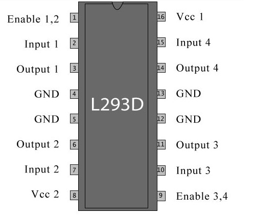
- Motor Driver(L293D)--This
project utilizes the L293D motor driver to control the motors of the wheel
chair. This is a typical Motor driver or Motor Driver IC that allows DC motor
to be driven in both directions. It is a 16-pin IC that can control a set of
two DC motors simultaneously in any direction. It means that two DC motors can
be controlled with just a single unit.It works on the concept of H-bridge. H-bridge is a circuit that allows the
voltage to be flown in either direction. Change in voltage changes the
direction, clockwise or anticlockwise. In a single chip, there are two H-bridge
circuits inside that rotate two dc motors independently. Due its size, it is
very much used in robotic application for controlling DC motors. Given below is
the pin diagram of a L293D motor controller.
There are 4 input pins, pin 2, 7 on the left and pin 15, 10 on the right as
shown on the pin diagram. Left input pins will regulate the rotation of motor
connected across left side and right input for motor on the right hand side.
The motors are rotated because of the inputs provided across the input pins as
LOGIC 0 or LOGIC 1.
Pin 2
|
Pin 7
|
Condition
|
1
|
0
|
Clockwise
Direction
|
0
|
1
|
Anti
clockwise
|
0
|
0
|
Idle
(High imepedance)
|
1
|
1
|
Idle
|
Table. 2.1 L293D
Logic Table.
Suppose a motor is connected on left side
output pins (pin 3, 6). For rotating the motor in clockwise direction, the
input pins have to be provided with Logic 1 and Logic 0.
Specifications:
The Atmel 8-bit AVR RISC-based
microcontroller combines 32 KB ISP flash memory with read-while-write
capabilities, 1 KB EEPROM,
2 KB SRAM, 23 general
purpose I/O lines, 32 general purpose working registers,
three flexible timer/counters with
compare modes, internal and external interrupts,
serial programmable USART, a
byte-oriented 2-wire serial interface, SPI serial port, 6-channel 10-bit A/D converter (8-channels in TQFP and QFN/MLF packages), programmable watchdog timer with internal oscillator, and five software selectable
power saving modes. The device operates between 1.8-5.5 volts. The device
achieves throughputs approaching 1 MIPS per MHz.
HC-05 module is an easy to use
Bluetooth SPP (Serial Port Protocol) module, designed for transparent wireless
serial connection setup. Serial port Bluetooth module is fully qualified
Bluetooth V2.0+EDR (Enhanced Data Rate) 3Mbps Modulation with complete 2.4GHz
radio transceiver and baseband. It uses CSR Bluecore 04-External single chip
Bluetooth system with CMOS technology and with AFH(Adaptive Frequency Hopping
Feature). It has the footprint as small as 12.7mmx27mm.
Hardware: Features
·
Typical -80dBm sensitivity
·
Up to +4dBm RF transmit power
·
Low Power 1.8V Operation ,1.8 to 3.6V I/O
·
PIO control
·
UART interface with programmable baud rate
·
With integrated antenna
·
With edge connector
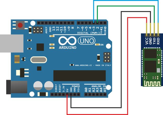
- Interfacing BT module with Arduino
The Figure 2.3 shows
interface between Arduino Uno and Bluetooth module HC05 and
The corresponding
connections.
The block diagram of the project is
as shown below.
The block diagram consists of
arduino Uno, Bluetooth module,motor drivr,motors,lead acid battery,ultrasonic sensors
and a smart phone consisting of Bluetooth.
The voice command from the phone is
transmitted by Bluetooth to the Bluetooth module(HC-05) which is connected to
the arduino.the motor drivers are used to drive the motors of the wheel.The
ultrasonic sensor(HC-SR04) measures the distance between the wheelchair and any
obstacle in front and prevents accidents.
Code:
#include <SoftwareSerial.h>
SoftwareSerial BT(10,11); //TX,RX respectively
String readvoice;
int in1=3;
int in2=4;
int in3=5;
int in4=6;
int pwm1=8;
int pwm2=9;
int pwm=255;
int trig=12;
int echo=13;
int time,dist;
void setup()
{
BT.begin(9600);
Serial.begin(9600);
pinMode(in1,OUTPUT);
pinMode(in2,OUTPUT);
pinMode(in3,OUTPUT);
pinMode(in4,OUTPUT);
pinMode(pwm1,OUTPUT);
pinMode(pwm2,OUTPUT);
pinMode(trig,OUTPUT);
pinMode(echo,INPUT);
}
void loop()
{
while(BT.available()) //Check if there is an avilable byte
{
delay(10);//Delay added to make thing stable
char c = BT.read(); //Conduct a serial read
readvoice += c; //build the string
}
digitalWrite(trig,LOW);
delayMicroseconds(5);
digitalWrite(trig,HIGH);
delayMicroseconds(10);
digitalWrite(trig,LOW);
time= pulseIn(echo,HIGH);
dist= (time/58.2);
Serial.println(dist);
delay(1000);
if(dist<90)
{
digitalWrite(in1,LOW);
digitalWrite(in2,LOW);
digitalWrite(in3,LOW);
digitalWrite(in4,LOW);
analogWrite(pwm1,pwm);
analogWrite(pwm2,pwm);
}
if(readvoice.length() > 0){
Serial.println(readvoice);
if(readvoice == "forward")
{
digitalWrite(in1,LOW);
digitalWrite(in2,LOW);
digitalWrite(in3,HIGH);
digitalWrite(in4,HIGH);
analogWrite(pwm1,pwm);
analogWrite(pwm2,pwm);
delay(500);
}
else if(readvoice == "back")
{
digitalWrite(in1,HIGH);
digitalWrite(in2,HIGH);
digitalWrite(in3,LOW);
digitalWrite(in4,LOW);
analogWrite(pwm1,pwm);
analogWrite(pwm2,pwm);
delay(1000);
digitalWrite(in1,LOW);
digitalWrite(in2,LOW);
digitalWrite(in3,LOW);
digitalWrite(in4,LOW);
}
else if(readvoice == "left")
{
digitalWrite(in1,LOW);
digitalWrite(in2,LOW);
digitalWrite(in3,LOW);
digitalWrite(in4,HIGH);
analogWrite(pwm1,pwm);
analogWrite(pwm2,pwm);
delay(1000);
digitalWrite(in1,LOW);
digitalWrite(in2,LOW);
digitalWrite(in3,LOW);
digitalWrite(in4,LOW);
}
else if(readvoice == "full left")
{
digitalWrite(in1,LOW);
digitalWrite(in2,LOW);
digitalWrite(in3,LOW);
digitalWrite(in4,HIGH);
analogWrite(pwm1,pwm);
analogWrite(pwm2,pwm);
delay(1500);
digitalWrite(in1,LOW);
digitalWrite(in2,LOW);
digitalWrite(in3,LOW);
digitalWrite(in4,LOW);
}
else if(readvoice == "right")
{
digitalWrite(in1,LOW);
digitalWrite(in2,LOW);
digitalWrite(in3,HIGH);
digitalWrite(in4,LOW);
analogWrite(pwm1,pwm);
analogWrite(pwm2,pwm);
delay(500);
digitalWrite(in1,LOW);
digitalWrite(in2,LOW);
digitalWrite(in3,LOW);
digitalWrite(in4,LOW);
}
else if(readvoice == "full right")
{
digitalWrite(in1,LOW);
digitalWrite(in2,LOW);
digitalWrite(in3,HIGH);
digitalWrite(in4,LOW);
analogWrite(pwm1,pwm);
analogWrite(pwm2,pwm);
delay(1000);
digitalWrite(in1,LOW);
digitalWrite(in2,LOW);
digitalWrite(in3,LOW);
digitalWrite(in4,LOW);
}
else if(readvoice == "stop")
{
digitalWrite(in1,LOW);
digitalWrite(in2,LOW);
digitalWrite(in3,LOW);
digitalWrite(in4,LOW);
delay(100);
}
readvoice="";}} //reset the variable
Conclusion:
Thus, by utilizing a
simple android device, this project was implemented. An application for android
was developed for the differently abled people to control the wheel chair using
simple voice commands. A bluetooth connection was established between the
android device and the wheelchair. Therefore, by doing so the cost of hardware
was reduced and its scope of implementation was greatly increased. Since the
application is based on android platform, future upgrades are solely dependent
on firmware updates. As the utilization of smartphones is exponentially
increasing in developing countries like India, this project aims to assist the
differently abled by means of these Android smartphones.
 The existing food ordering system in most of the hotels is entirely a manual process which
involves waiters, pen and paper. The waiter had to get order from customers, take these orders
to kitchen, update them in records and again generate bill for the ordered food. Even though
this system is simple it may involve human errors in noting down the orders, forwarding it to
chef, and finally calculating the bill. To overcome these limitations in manual system some
systems were developed like PDA (Personal Digital Assistant) based systems and multi touchable
restaurant management systems to automate food ordering process. Our main
motivation is to completely automate the ordering process in restaurants and hotels to improve
the efficiency and reduce the problems faced by the customers.
The existing food ordering system in most of the hotels is entirely a manual process which
involves waiters, pen and paper. The waiter had to get order from customers, take these orders
to kitchen, update them in records and again generate bill for the ordered food. Even though
this system is simple it may involve human errors in noting down the orders, forwarding it to
chef, and finally calculating the bill. To overcome these limitations in manual system some
systems were developed like PDA (Personal Digital Assistant) based systems and multi touchable
restaurant management systems to automate food ordering process. Our main
motivation is to completely automate the ordering process in restaurants and hotels to improve
the efficiency and reduce the problems faced by the customers.
 This system is implemented to enhance the security and protect the device against thefts.
Figure below shows the circuit diagram of the buzzer circuit which will be attached to an
android phone or a tablet. If a customer tries to pull the phone/tablet out of its position, the
buzzer will ring with a noticeable sound. It is powered by a 9V battery.
This system is implemented to enhance the security and protect the device against thefts.
Figure below shows the circuit diagram of the buzzer circuit which will be attached to an
android phone or a tablet. If a customer tries to pull the phone/tablet out of its position, the
buzzer will ring with a noticeable sound. It is powered by a 9V battery.